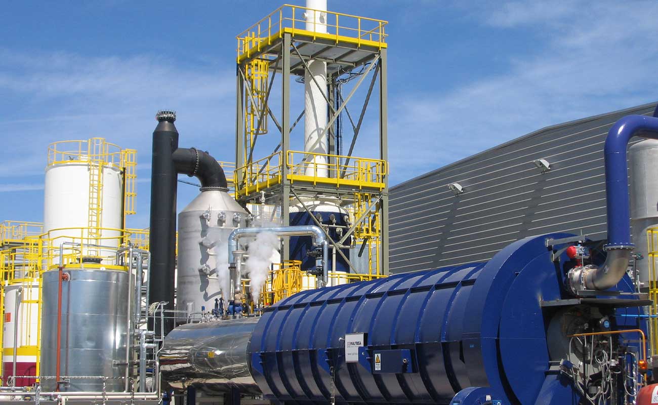
WASTE TO ENERGY
Waste to energy (WTE) consist of the recovery of thermal energy generated in a waste incineration process. The gases generated in thermal destruction processes are exhausted from the kiln at a high temperature (between 850 and 1100ºC), the use of this heat energy is the target of waste to energy.
Valorization facilites mainly have 4 different stages:
- Feeding with such as elevators, worm drives, mud pumps, liquid injection spears, etc.
- Thermal destruction, in continuous rotatory kilns or in static kilns, depending on the waste type.
- Energy recovery, thourgh:
- Water steam, hot watre or thermal oil boilers;
- Electric turbine (ORC);
- Gas-air heat exchangers;
- Leachate quenchs;
- ...
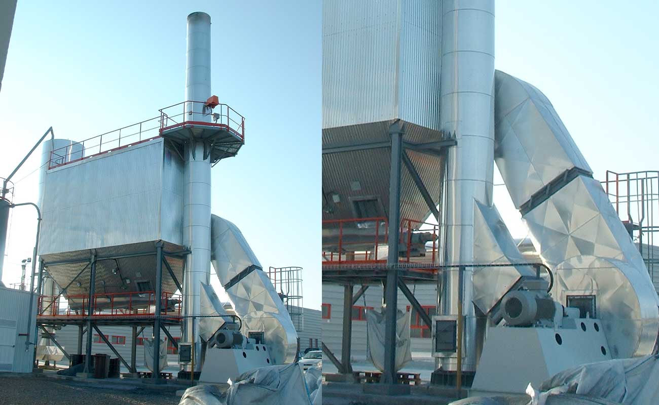
- Gas cleaning: the generated gases are physically and chemically purified to be exhausted to the atmosphere in accordance with current environmental regulations.
Almost 60 years of experience in the design of incinerator kilns support us to offer solutions for the energy recovery of waste, through its thermal destruction.
Our installations exceed the minimun energetic efficiency (0,65) required by the Directive 2008/98/EC of the European Parliament and of the Council, for R1 waste recovery operations (waste to energy).
At Kalfrisa we tailor our equipment to our client's needs, offering 360° solutions, an integral service that includes design, manufacturing, assembly, and commissioning of the complete WTE facility.

Sectors
- Refuse Derived Fuel (RDF).
- Dangerous waste.
- Hospital waste.
- Liquid waste (solvents, paraffins, contaminated water...).
- Sewage sludge.
- Landfills (capacity reduction).

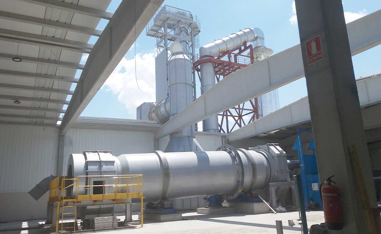
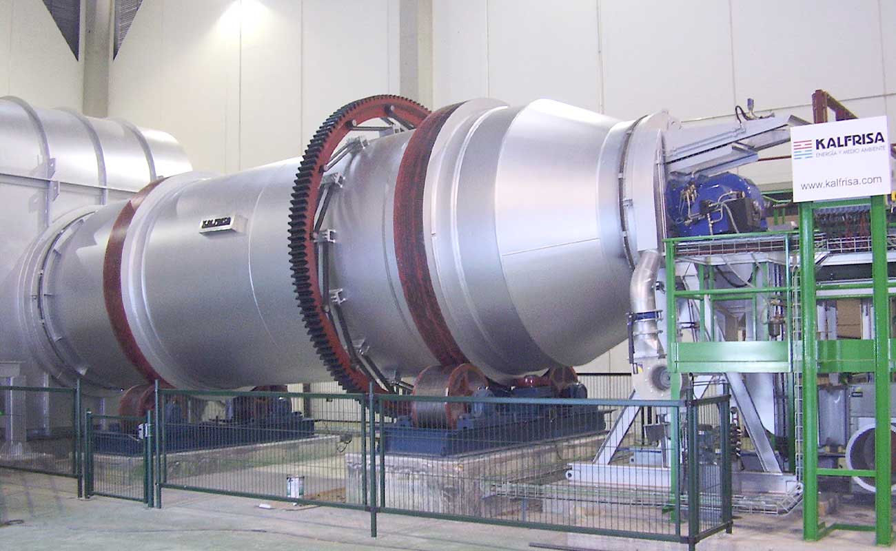
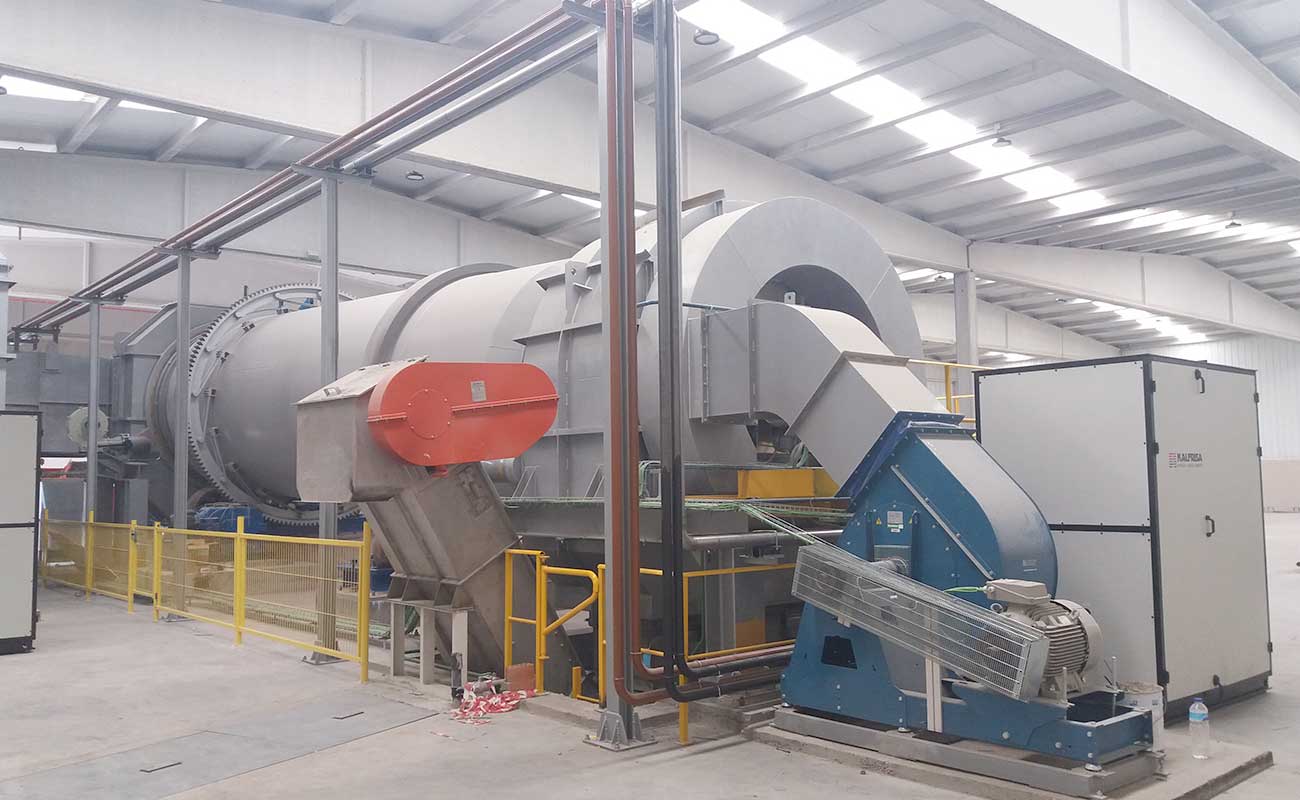
SOLID OR PASTY WASTE
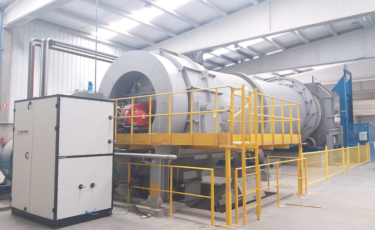
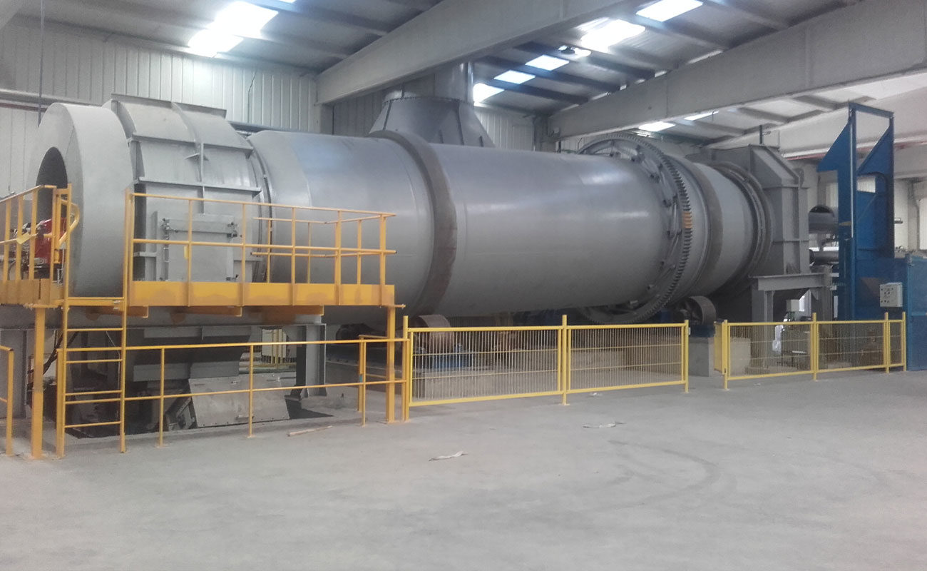
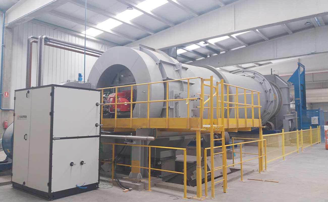
Continuous rotatory kilns
KR models are rotatory kilns ready to work continuously 24/7, which stand out for their robustness and versatility.
The combustion chamber of the kilns is cylindrical, and it is internally lined with insulating and refractory materials.
On one edge of the chamber, the corresponding feeding system (auger, piston pump, container elevators, etc, depending on each case) and the industrial burner for the waste destruction are installed. On the opposite edge, the afterburner chamber is installed. There the oxidation of the combustion gases takes place, and they are thermally purified.
Furthermore, in the lower part of the afterburner, a continuous ash extraction system allows uninterrupted work.
KR-20,000 | KR-30,000 | KR-40,000 | KR-70,000 | |
Destruction capacity (kg/h)* | 600-900 | 900-1.500 | 1.500-2.500 | 2.500-4.000 |
Chamber volume (m3) | 20 | 30 | 40 | 70 |
Recoverable energy (KW)* | 1.500-2.500 | 2.500-4.500 | 4.500-6.500 | 6.500-10.500 |
* approximate values: final value based on the residues’s LHV
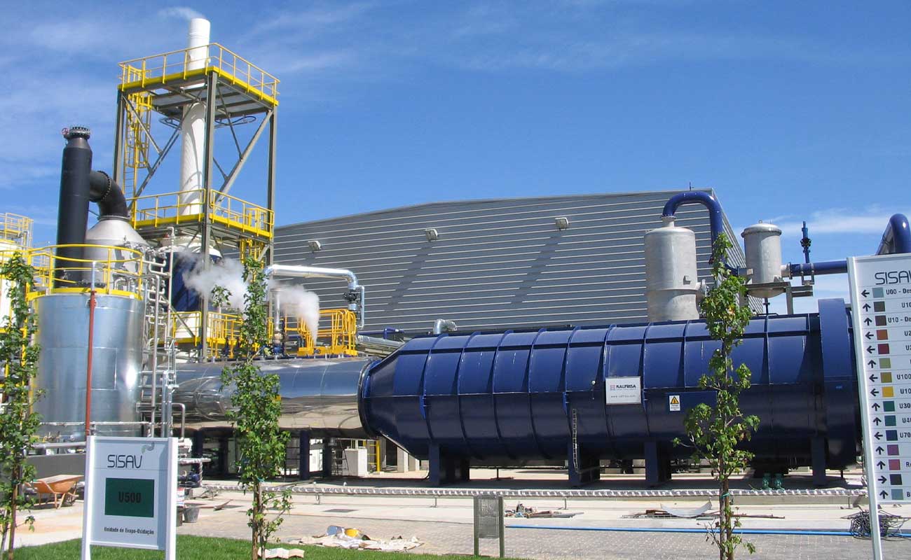
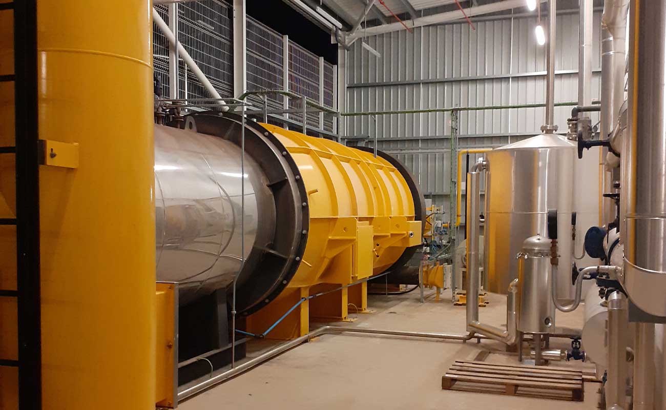
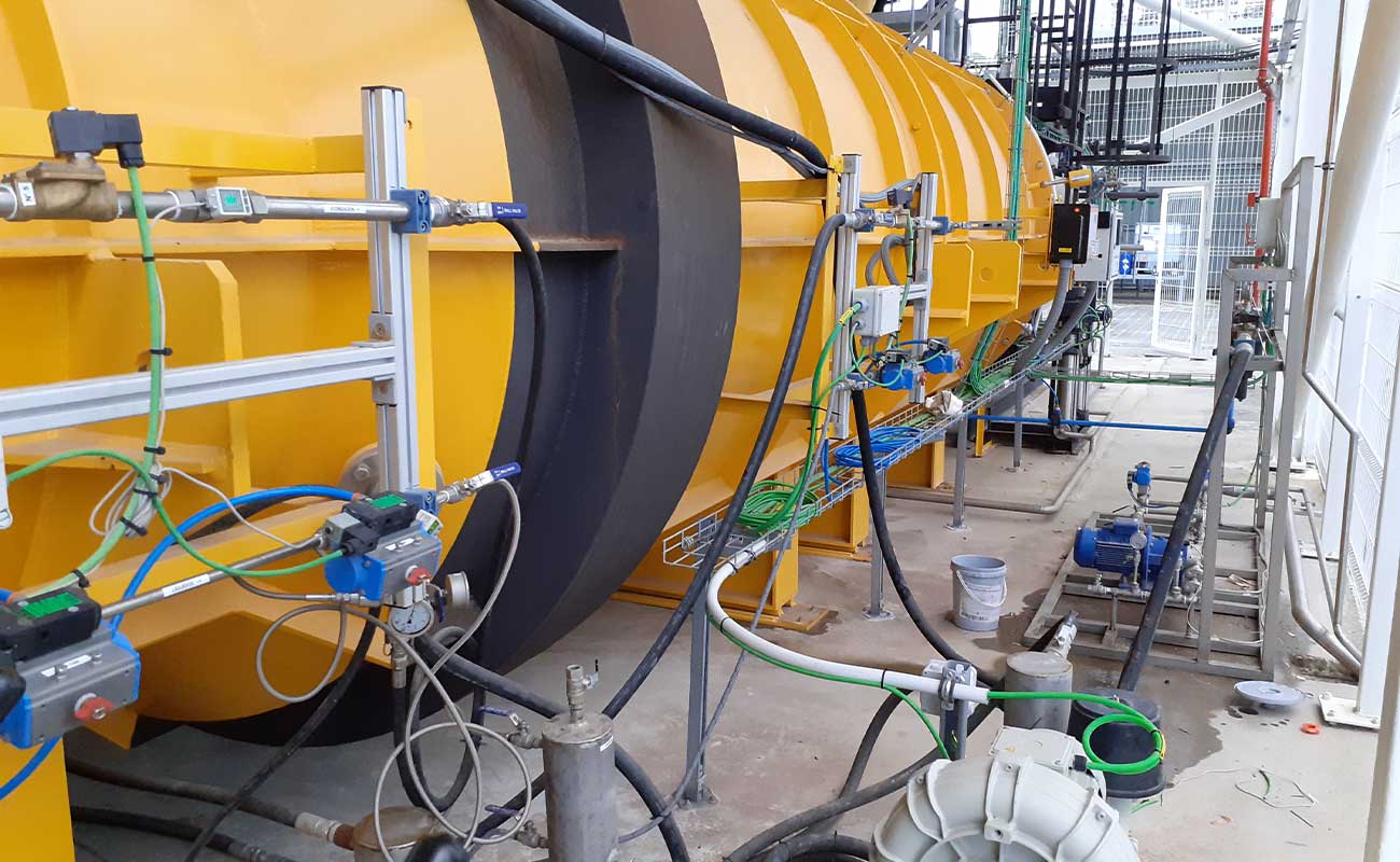
LIQUID WASTE
Static kilns
KL models are static kilns specially designed to destroy liquid waste, which can be pumpable
Their combustion chamber has a cylindrical shape and it is lined internally with insulating and refractory concrete.
The waste is introduced using pneumatic injection lances, located at one end of the combustion chamber. At that same end the industrial burner is installed for the destruction of waste.
KL-2500 | KL-12.500 | KL-20,000 | KL-35,000 | |
Destruction capacity (L/min)* | 3-5 | 15-20 | 30-35 | 50-55 |
Chamber volume (m3) | 2,5 | 12,5 | 20 | 30 |
Recoverable energy (KW)* | 500-750 | 1.500-1.750 | 2.500-2.750 | 4.000-4.500 |
* approximate values: final value based on the residues’s LHV